
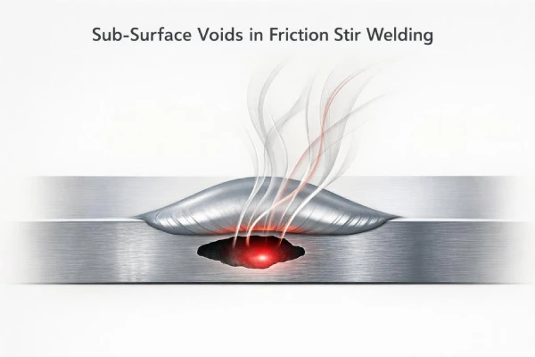
Friction stir welding looks calm on the surface, but a single sub-surface void can mandate expensive rework on the assembly line. In aerospace, undetected volumetric defects can cost up to $10,000 per meter to repair.
A 2025 Grand View Research report highlights a surging demand for defect-free lightweight joining in EV and aerospace manufacturing, where scrap rates destroy margins during full-scale production.
As a Supro Friction Welding process engineer noted, “Voids don’t start in the metal. They start in parameter control.”
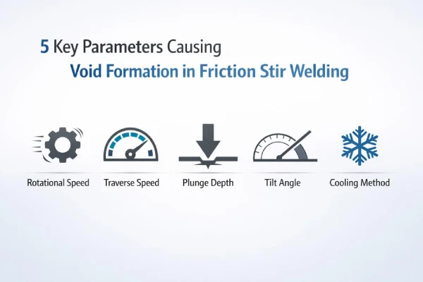
5 Key Parameters Causing Void Formation
Void defects in friction stir welding occur when friction, stir, and consolidation forces fall out of sync during the joining process. Here is the engineering breakdown of void initiation.
Rotational Speed Effects on Void Initiation in Desktop FSW Unit
In a Desktop FSW Unit, Rotational Speed dictates the strain rate and Heat Generation, establishing Material Flow.
Tool Rotation & Heat Balance
1)Low rpm
↓ Plasticization (failing to reach the 350-400°C window for AA7075 during operations)
Incomplete flow around pin
↑ Void Initiation
2)Excess rpm
Overheating and flash formation
Detrimental grain coarsening
Welding Defects Linked to Speed
Tunnel voids from cold stir zones in joint areas
Kissing bonds from weak consolidation
Surface galling from unstable friction stir welding
Supro Friction Welding strictly tunes the pitch ratio (RPM to traverse speed) on compact systems, ensuring stable plasticization even in critical thin-gauge aluminum panels.
Traverse Speed: Balancing Heat Input in Aluminum Alloys
Traverse Speed governs the Heat Input and Thermal Cycle in Aluminum Alloys.
| Welding Speed (mm/min) | Avg. Heat Input (kJ/mm) | Observed Microstructure | Joint Integrity |
|---|---|---|---|
| 80 | 1.25 | Fine DRX grains | High |
| 150 | 0.95 | Mixed structure | Moderate |
| 220 | 0.60 | Incomplete recrystallization | Low |
| 300 | 0.45 | Cold lap tendency | Poor |
Speed too high
Short thermal exposure
Weak Microstructure evolution leading to Incomplete recrystallization defects
Speed optimized
Balanced stir welding flow
Reliable Joint Integrity
Plunge Depth Control with Gantry FSW System Tool Geometry
On a Gantry FSW System, Plunge Depth drives the necessary forging pressure via Tool Geometry. Variances of just ±0.05 mm can degrade shear strength by 20% across the assembly.
Penetration Depth Control
1)Shallow plunge
Poor root bonding
Reduced Axial Force
2)Excess plunge
Tool shoulder gouging
Surface thinning
Process Stability Chain
Correct Tool Design
Stable Workpiece Interaction
Consistent forge pressure
Sound friction stir welding root
Supro Friction Welding utilizes dynamic load feedback to calibrate plunge settings, guaranteeing tight joints from crown to root.
Need to Optimize Your Welding Parameters? At Supro Friction Welding, we engineer customized automated Solutions with flexible parameter ranges (up to 500 tons of forging force and 8,000 RPM) to eliminate defects. When you reach out and Contact us today, our engineering team will provide a free test weld evaluation to determine your optimal process parameters.
Tilt Angle Optimization Using FSW Tool Shoulder
The Tilt Angle determines how the FSW Tool Shoulder traps and forges plasticized metal.
Tool Inclination Effects
1)0°
Weak forging
Risk of tunnel defects
2)2.5° (Industry Optimum for 6xxx Al processing)
Improved Material Consolidation
Smoother Surface Finish
3)4°
Excess flash
Shoulder wear
Cooling Method Selection for Titanium Alloys
With Titanium Alloys (like Ti-6Al-4V), cooling rates exceeding 50°C/s are critical to control Microstructural Evolution and mitigate alpha-case embrittlement effectively.
Heat Dissipation Paths
1)Air cooling
Slower Solidification
Lower stress gradient
2)Backing plate chill
Rapid heat draw
Flow restriction risk
Post-Weld Treatment Flow
Controlled cooling
Microhardness scan
Stress relief cycle
Mechanical validation
Supro Friction Welding aligns thermodynamic cooling profiles with real-time process data to eliminate void formation in reactive metals, a critical focus within our custom Solutions engineered for advanced applications.
Does Excessive Travel Speed Cause Voids?
Excessive traverse speed actively disrupts force balance and material mixing, serving as a primary catalyst for internal cavity formation inside the joint.
How Traverse Speed Influences Axial Force and Void Growth
Traverse Speed directly dictates Axial Force stability. Force drops exceeding 15% immediately trigger void tunnels, predominantly on the advancing side.
Process Parameters Interaction
1)Heat Input
Higher Traverse Speed → shorter tool–material contact time
Reduced plasticization in the Material Flow zone
2)Force Stability
Fluctuating Axial Force
Reduced forging pressure behind the pin
Void Growth Mechanism
Stage 1: Insufficient softening in advancing side
Stage 2: Incomplete backfill at tool exit
Stage 3: Micro-voids link → internal tunnel defects
Key signals operators watch:
Sudden torque dips
Irregular spindle load
Surface thinning near the weld crown
At Supro Friction Welding, balancing tool rotation with traverse speed is a non-negotiable standard to arrest Void Growth.
Microstructure Analysis of Dissimilar Metals at High Speeds
High-speed welding of Dissimilar Metals disrupts atomic diffusion. For instance, Al-Cu joints require intermetallic layers to remain <2 microns to avoid brittle fracture.
In the Weld Zone, rapid travel can:
Distort Grain Structure
Trap fragmented phases
Along the interface:
Thin, uneven Intermetallic Compounds
Reduced Interface Integrity
Common microstructural findings:
Heterogeneous grain bands
Clustered void pockets
Weak bonding islands throughout the interface
“Process stability remains the primary determinant of weld integrity in high-speed solid-state joining,” notes the 2025 Global Welding Automation Outlook by MarketsandMarkets, highlighting force fluctuation as a leading indicator of internal defect formation.
Supro Friction Welding relies on strictly controlled trials before scaling dissimilar joints, proving that uncalibrated speed is an inherent liability.
Scale Production Without Defects** Struggling with high scrap rates in dissimilar metal joints? Leverage our 40 years of experience and robust portfolio of 277 patents. Explore our Contract Friction Welding Services to resolve dissimilar metal challenges, or upgrade your assembly line with an automated Rotary Friction Welding Machine designed to eliminate manual variability.
Real-Time Defect Detection via Data Acquisition System
Advanced FSW setups integrate Data Acquisition Systems to predict defects via predictive machine learning algorithms, reducing high-volume scrap by up to 40%.
Sensor Layer
Acoustic Emission (AE) sensors
Load cells measuring Axial Force
Temperature probes in the tool holder
Signal Processing Layer
Raw Sensor Data filtering
Pattern recognition for instability
Threshold alarms for Void Identification
Process Control Response
Automatic speed reduction
Rotation compensation
Adaptive plunge correction
Within systems utilized by Supro Friction Welding, the FSW Robotics System bridges force feedback to adaptive speed control, neutralizing voids autonomously.
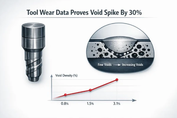
Tool Wear Data Proves Void Spike By 30%
Tool wear physically alters heat flow and material mixing geometries, directly elevating defect rates.
FSW Tool Pin Wear: Correlating Wear Rate with Void Density
Tracking FSW, Tool Pin Wear, and Wear Rate establishes a direct Correlation with Void Density and Sub-Surface Voids.
Wear progression
1)Geometry loss
Reduced pin length → weaker material plunge
Rounded threads → lower stir intensity
2)Surface abrasion
Less friction heat
Poor material flow
Measured production data
| Tool Hours | Wear Rate (mm/hr) | Void Density (%) | Sub-Surface Voids (count/m) |
|---|---|---|---|
| 50 | 0.02 | 0.8 | 1 |
| 100 | 0.05 | 1.6 | 3 |
| 150 | 0.09 | 2.4 | 5 |
| 200 | 0.14 | 3.1 | 8 |
Supro Friction Welding monitors this degradation curve to prevent the near 30% void spike associated with end-of-life tools.
Degradation of Tool Shoulder and Its Impact on Weld Integrity
Tool Shoulder Degradation reduces contact area, directly suppressing forging pressure. In Friction Stir Welding, this compromises Weld Integrity.
Friction loss
Reduced heat input
Irregular material consolidation
As Tool Wear compounds, Void Formation spike in Magnesium and Copper Alloys drastically. Supro Friction Welding aggressively regulates rotational and axial force variables once shoulder thinning is detected.
Tool Material Selection to Minimize Wear in Polymer Composites
For Polymer Composites, implementing advanced Tool Material like PCBN guarantees Wear Minimization and Tool Durability.
Material pairing logic
1)Hardness match
Too hard → surface tearing
Too soft → rapid erosion
2)Thermal behavior
Stable heat window
Controlled friction
Performance outcome
Stable stir welding temperature
Balanced friction generation
Lower void rate
We Offer Financial & Superior Services
A small river named Duden flows by their place and supplies it with the necessary
regelialia. It is a paradisematic country, in which
FAQs about Friction Stir Welding
1.How does rotational speed influence void formation in friction stir welding?
Low Rotational Speed → weak plastic flow in Aluminum Alloys and Magnesium Alloys
Excessive speed → overheating, tool wear on the FSW Tool Pin
Stable control through FSW Control Software keeps Axial Force and heat input aligned
In a Desktop FSW Unit or Gantry FSW System, optimized speeds mitigate tunnel defects during Non-Destructive Testing.
2.Why does traverse speed determine weld integrity in production lines?
Traverse Speed dictates dwell time under the FSW Tool Shoulder.
High Traverse Speed
Limited material mixing
Weak bonding in Dissimilar Metals
Low Traverse Speed
Excessive heat buildup
Grain coarsening in Copper Alloys
Through Simulation Software within an FSW Robotics System, operators preserve fine microstructure for Mechanical Property Testing.
3.Can incorrect plunge depth and tilt angle weaken weld roots?
Yes.
Insufficient Plunge Depth limits FSW Tool Pin engagement.
Poor Tilt Angle reduces contact efficiency of the FSW Tool Shoulder.
Reduced Axial Force leaves root gaps in Titanium Alloys or thick Aluminum Alloys.
A calibrated Gantry FSW System, supported by Calibration Services and our dedicated Technical Support Services team, safeguards the weld root.
4.How do manufacturers maintain tool life and quality across different materials?
Maintenance combines:
High-grade Tool Material selection stored in a managed Spare Parts Inventory
Real-time torque tracking via a Data Acquisition System
Scheduled inspection of the Tool Cartridge and Tool Geometry
Weld Inspection Systems and Operator Training Programs ensure consistent handling across every Friction Stir Welding Machine.
Discover Supro Friction Welding Solutions
With over 40 years of industry leadership, 277 registered patents, and ISO 9001 certification, Supro Friction Welding engineers automated, zero-defect welding systems for aerospace, EV, and high-strength applications.
Whether you require a custom Continuous Drive Friction Welding Machine, an Inertia Friction Welding Machine, or highly specialized welding operations, our integrated OEM/ODM equipment ensures a strict “100% Cosmetic Grade” standard and unparalleled joint integrity.
Ready to eliminate production defects and scale your capacity? Explore our successful Case Studies to see real-world results, or Contact Us today for a free test weld evaluation, lifetime Technical Support Services, and expert process consultation!
References
Friction stir welding – Wikipedia
mandate expensive rework – TWI Global
undetected volumetric defects – Thomasnet
2025 Grand View Research report – Grand View Research
scrap rates destroy margins – ScienceDirect
consolidation forces fall out of sync – American Welding Society
strain rate – NASA Technical Reports Server
350-400°C window for AA7075 – MDPI
Tunnel voids from cold stir zones – Taylor & Francis Online
Thermal Cycle – SpringerLink
Incomplete recrystallization – Nature
degrade shear strength by 20% – Frontiers
dynamic load feedback – Hindawi
Industry Optimum for 6xxx Al – Wiley Online Library
mitigate alpha-case embrittlement – MDPI
internal cavity formation – PubMed Central
Force drops exceeding 15% – DTU Orbit
Al-Cu joints require intermetallic layers to remain <2 microns – PubMed Central
Weak bonding islands – Penn State University
predictive machine learning algorithms – ResearchGate