
Rotary friction welding has become an indispensable foundational joining technology in sectors such as aerospace, heavy-duty energy, and automotive manufacturing. Offering joint strength that exceeds that of the base materials, excellent metallurgical integrity, and high compatibility with dissimilar metals, it addresses the challenges of cracking and performance degradation faced by traditional fusion welding. As Industry 4.0 imposes increasingly stringent requirements for lightweight components and near-net-shape manufacturing, the rotary friction welding process is redefining the manufacturing standards for high-load structural components.
However, for senior procurement managers and structural engineers, the real technical challenge when dealing with specific projects lies in making the most scientifically sound choice between inertial friction welding and continuous drive friction welding. This is not merely a difference in the method of energy input; it directly impacts the control of the heat-affected zone (HAZ) width, the precision tolerances of axial dimensions, and the cost-effectiveness per unit in high-volume production. An incorrect choice may result in grain coarsening of the material or excessive machining allowances, thereby impacting the ROI of the entire supply chain.
Drawing on Supro MFG’s extensive engineering expertise in rotary friction welding, this article provides an in-depth analysis of the core mechanisms and application limits of these two processes. Starting with a pressure range spanning from 2 to 1,200 tons, we will examine how our rotary friction welding machines overcome the challenges of welding large-diameter workpieces. We will also present a decision-making framework that addresses production volume, material sensitivity, and tolerance requirements, offering you technical insights of the highest commercial value.
Understanding the Mechanics of Rotary Friction Welding
Based on the method of energy input, the types of rotary friction welding widely used in modern industry are primarily divided into two categories: inertial friction welding (IFW) and continuous drive friction welding. IFW relies on kinetic energy stored in a flywheel system, while the other method is continuously powered by a drive motor. Although both utilize the same basic principle, there are significant differences in equipment configuration, process control, and application scenarios; therefore, they are suited for different production needs and product requirements. Understanding the fundamental differences between these two friction welding processes is the first step toward making the right technical choice.
What is Inertial Friction Welding ?
The technical principle involves accelerating the flywheel system in advance to store kinetic energy. When the workpieces come into contact, the stored energy is converted into thermal energy through friction, achieving a high-quality material joint. The welding process for this type of rotary friction welding machine primarily proceeds through three stages:
Energy Storage Stage—The friction welding machine system drives the flywheel and workpieces to a preset rotational speed, storing a large amount of kinetic energy in the rotating flywheel system.
Release and Friction Stage — After the drive cycle ends, the rotating component continues to spin and comes into contact with the stationary workpiece on the opposite side under the axial pressure of the rotary friction welding machine.
Upsetting and Forming Stage — Kinetic energy is rapidly converted into thermal energy at the contact interface. Combined with the upsetting pressure, this causes the plasticized metal material to extrude, simultaneously achieving metallurgical bonding at the interface, thereby completing the friction welding process.
Compared to traditional welding methods, inertial friction welding features low heat input, minimal deformation, and narrow welds. It is one of the few processes capable of achieving a true 6σ quality level (defect rate below 3.4 parts per million), and with a welding cycle of only a few seconds, it is well-suited for batch production of rotary friction welding.
Ideal Applications for Inertial Friction Welding
IFW is suitable for a wide range of materials and is also an excellent process for friction welding of dissimilar materials. Typical applications include manufacturing sectors such as aerospace, automotive, oil exploration, and general industry.
For aerospace components, where fatigue performance and joint strength requirements are stringent, inertial friction welding is well-suited to meet these demands. Typical products include engine rotors, turbine shafts, and compressor discs.
In the automotive and oil exploration sectors, inertial friction welding is frequently used to join circular-section structural components such as drive shafts, axles, piston rods, and drill pipes. Its rapid forming capability facilitates high-strength, high-precision mass production.
What is Continuous Drive Friction Welding?
Although both processes involve heating materials by generating heat through rotation and friction, their operating principles differ. In continuous drive friction welding, an electric motor continuously rotates one workpiece while pressing another workpiece against it, causing the contact surfaces to rub against each other and generate heat and plastic deformation. The rotation is then stopped, and forging pressure is applied to complete the weld.
The working stages of continuous drive friction welding can be divided into two steps:
Friction stage—Under the continuous drive of the rotary friction welding machine’s motor, the workpiece rotates according to a preset program. The other workpiece remains in contact with the rotating workpiece under stable axial pressure until the entire contact surface reaches a uniform thermoplastic state.
Upsetting stage—Once the preset conditions are met, the rotation stops. Simultaneously, the rotary friction welding machine applies immense upsetting pressure to compress the two workpieces, thoroughly removing all oxides, impurities, and defects from the weld interface. This achieves a dense metallurgical bond between the pure metals.
The key advantage of this rotary friction welding process lies in its ability to independently and precisely control friction welding parameters, enabling greater flexibility in process adjustments and making it particularly suitable for welding dissimilar materials with significantly different thermal and physical properties.
Ideal Applications for Continuous Drive Friction Welding
This rotary friction welding process demonstrates exceptional material compatibility. Not only does it efficiently weld common metallic materials such as carbon steel, alloy steel, and aluminum alloys, but it is also the preferred process for friction welding dissimilar metals, enabling reliable joints between materials such as steel and aluminum or copper and steel. It is widely used in the automotive, oil exploration, industrial, and electrical sectors.
In the field of oil exploration, drilling and production equipment must withstand harsh conditions such as deep wells and high pressure. The characteristics of continuous drive friction welding make it the core process for connecting drill pipes and casing. The welded joints offer excellent torsional strength and corrosion resistance, enabling them to effectively withstand complex underground geological conditions and fluid erosion, thereby significantly reducing the risk of failure in rotary friction welding machines during drilling and production operations.
In the industrial sector, continuous drive friction welding is commonly used to weld large, thick-walled rotating structural components. Typical applications include the boom connection shafts of excavators and the boom pins of cranes, which are capable of withstanding high-intensity impact loads and alternating stresses.
Supro offers a wide range of Inertia Friction Welding Machines and Continuous Drive Friction Welding Machines. Our friction welding equipment is equipped with advanced control systems, enabling us to meet the manufacturing needs of customers across multiple industries. Additionally, we undertake various welding projects, achieving high-strength, high-precision mass production and ensuring 100% product quality.
Technical Differences Between Two Types of Rotary Friction Welding
Before delving into the specific technical details, it is essential to understand the technical differences between the two modes of rotary friction welding. Although both fall under the category of solid-state joining, there is a fundamental difference in how friction welding energy is applied. The “instantaneous release of kinetic energy” from the flywheel and the “constant power input” from the spindle motor directly determine the microstructural quality, dimensional accuracy, and production efficiency of the joint.
Heat-Affected Zone & Microstructure Integrity
As a solid-state welding technique, rotary friction welding offers the key advantage of operating at temperatures below the material’s melting point. In this process, the width and evolution of the heat-affected zone (HAZ) depend on the energy input mode:
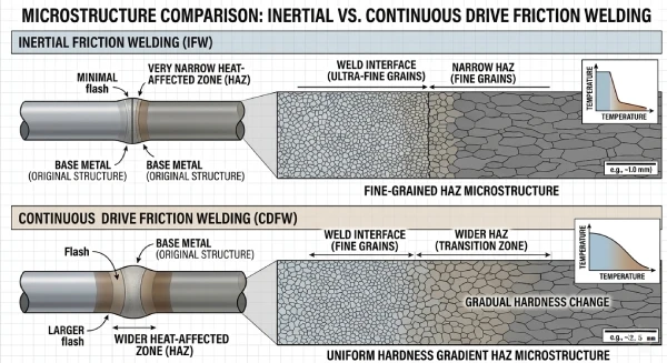
Inertial friction welding (IFW): Because the flywheel releases kinetic energy extremely rapidly, heat is concentrated in a narrow area. This “instantaneous high pressure” produces extremely fine recrystallized grains, resulting in an extremely narrow HAZ. For titanium alloys or high-temperature nickel-based alloys, inertial friction welding effectively prevents grain coarsening and maintains excellent microstructural integrity.
Continuous drive friction welding (CDFW): The continuous input of constant power results in a slightly longer heat conduction time, producing a relatively wider heat-affected zone. However, when processing large batches of carbon steel or stainless steel components, continuous drive friction welding provides a more uniform hardness gradient and prevents embrittlement at the joint interface.
Precision Control: Dimensional Accuracy vs. Cycle Efficiency
Continuous drive friction welding offers greater advantages in terms of axial dimensional control. Because the spindle speed remains constant, friction welding equipment can actively brake and apply upsetting pressure when reaching a precise position based on a preset “upsetting amount.” The active control logic of continuous drive friction welding enables the total length tolerance of finished products to be controlled within an extremely narrow range during high-volume production (such as hydraulic rods or pump shafts), significantly reducing the amount of subsequent machining required.
In contrast, inertial friction welding offers a significant advantage in terms of cycle efficiency—thanks to the instantaneous release of energy from the flywheel, the welding process can be completed in just a few seconds. However, the reduction in cycle time achieved by inertial friction welding is limited by the complete dissipation of the initial kinetic energy, resulting in slightly greater tolerance fluctuations compared to continuous drive friction welding.
Flash Formation & Flash Management
Rotary friction welding is a solid-state welding technique; when metal is extruded into the weld seam under high temperature and pressure, curled flash tends to form.
Inertial friction welding involves extremely rapid energy input, resulting in flash that typically forms a tighter, more uniform spiral. The heat-affected zone is narrow, and mechanical stress during machining is reduced.
Due to the constant power input characteristic of continuous drive friction welding, the flash extruded after welding may be relatively wide and thick. However, thanks to the high adjustability of the process parameters, it is easier to control the exact volume of the flash.
Supro MFG employs advanced “in-process flash removal” technology, using an integrated cutting tool to remove flash directly after the rotary friction welding cycle ends, while the workpiece is still warm. This process significantly reduces the time required for secondary machining, ensuring that parts delivered to customers exhibit excellent near-net-shape characteristics and substantially lowering the total production costs of friction welding projects.
Rotary friction welding for large-scale applications in heavy industry
The upper limit of a rotary friction welding machine’s capacity directly determines the design constraints for parts. Whether it’s sensor assemblies requiring extreme micron-level precision or massive drilling tools subjected to extreme loads, precise control of friction welding pressure is key to ensuring joint strength.
Overcoming the Challenges of Large-Diameter Joining
An increase in workpiece diameter results in a significant rise in the surface velocity gradient—the difference in circumferential velocity between the edge and the center—which can easily lead to insufficient heat in the central region or overheating at the edges during rotary friction welding. Supro MFG has successfully overcome this technical challenge by manufacturing a 1,200-ton rotary friction welding machine.
The rotary friction welding machine’s powerful 1,200-ton forging force ensures that heavy-duty components can fully expel oxides during the plastic deformation stage, resulting in a pore-free molecular bond.
When processing large-diameter solid shafts or thick-walled tubular components, the rotary friction welding machine’s precise torque compensation technology effectively prevents residual stress caused by uneven heating of the material.
This rotary friction welding solution for heavy-duty components offers superior fatigue strength and structural reliability compared to traditional arc welding for oil drilling pipes, aircraft engine spindles, and heavy-duty mechanical drive shafts. It is a reliable rotary friction welding process for achieving near-net-shape manufacturing of large-scale components.
Engineering Capabilities: From 2-Ton Precision to 1200-Ton Power
Supro MFG’s technology portfolio covers a full range of rotary friction welding pressure ratings from 2 tons to 1,200 tons, meeting the extreme requirements for heat input and forging pressure across parts of various sizes:
2-Ton Precision’s rotary friction welding machine is primarily designed for applications in electronic medical devices, sensors, and micro-shafts, offering extremely high rotational speeds and micrometer-level displacement control to ensure that thin-walled parts do not undergo buckling or deformation.
The 1200-Ton Power rotary friction welding machine is specifically designed for large-diameter solid components in heavy-duty industries such as aerospace and oil and gas drilling. With a 1,200-ton upsetting force, it enables rotary friction welding of components with extremely large cross-sections, ensuring that joint strength exceeds that of the base material even under harsh high-pressure and high-load conditions.
This comprehensive range of processing capabilities, combined with our one-stop contract manufacturing services, makes Supro MFG the partner of choice for engineers worldwide tackling complex mixed-metal joining and near-net-shape projects.
We Offer Financial & Superior Services
A small river named Duden flows by their place and supplies it with the necessary
regelialia. It is a paradisematic country, in which
How to choose the right rotary friction welding process?
In the field of rotary friction welding, there is no single “best” process; rather, there is only the solution that best meets the specific project requirements. For global buyers, the choice between inertial drive and continuous drive essentially comes down to striking a balance between technical specifications, production efficiency, and material costs.
Factors to Consider: Volume, Material, and Tolerance
Production Volume: Continuous drive friction welding is typically the preferred solution for high-volume projects. Thanks to its highly automated parameter control and consistent cycle times, it offers significant cost efficiency when processing tens of thousands of standardized parts, such as automotive half-shafts.
Material sensitivity: For aerospace-grade materials (such as titanium alloys or single-crystal superalloys), inertial friction welding delivers superior performance. The extremely rapid heat input minimizes grain coarsening, ensuring the metallurgical integrity of the joint under extreme conditions.
Tolerance Requirements: If your design imposes strict limits on the total length after welding, the active braking mechanism of continuous drive friction welding provides micrometer-level control over axial displacement. For heavy-duty workpieces that allow for some variation in length but require higher joint strength, inertial friction welding is the more reliable choice.
Supro MFG recommends conducting a DfM review early in the project. By analyzing your bill of materials and tolerance specifications, we can identify the most cost-effective, high-performance rotary friction welding solution for you, ensuring that every dollar of your budget translates into exceptional product quality.
Cost-Benefit Analysis: Near-Net Shape Manufacturing
Rotary friction welding precisely joins standardized profiles of different specifications. Compared to traditional machining from solid or arc welding, it significantly reduces waste of expensive raw materials. Particularly when working with aerospace-grade titanium alloys or stainless steel, the rotary friction welding process allows engineers to use high-performance materials only in critical areas, while employing lower-cost carbon steel for the remaining parts, thereby improving material utilization by 30% to 60%. At the same time, the joints produced by friction welding are extremely strong and require minimal material allowance, significantly reducing subsequent finishing time.
Supro MFG offers a full range of rotary friction welding capabilities, from 2 tons to 1,200 tons, enabling us to help global customers achieve shorter lead times and lower unit costs through Design for Manufacturing (DfM) optimization from the earliest stages of design. By selecting the most suitable rotary friction welding process, your project will not only achieve exceptional weld quality but also maintain a cost advantage in the global marketplace.
Contact Supro-mfg
In summary, as a cutting-edge solid-state joining technology, rotary friction welding is providing reliable support for global high-precision manufacturing through the complementary use of inertial and continuous drive processes. With a pressure range spanning 2 to 1,200 tons, Supro MFG has not only overcome welding bottlenecks for large-diameter, heavy-duty components but has also achieved significant near-net-shape benefits through Design for Manufacturing optimization.
Whether you are pursuing exceptional microstructural integrity or strict dimensional tolerances and cost control in friction welding, selecting the rotary friction welding process that best aligns with your project’s specific requirements will be a core strategy for optimizing your supply chain and enhancing your products’ global competitiveness.