
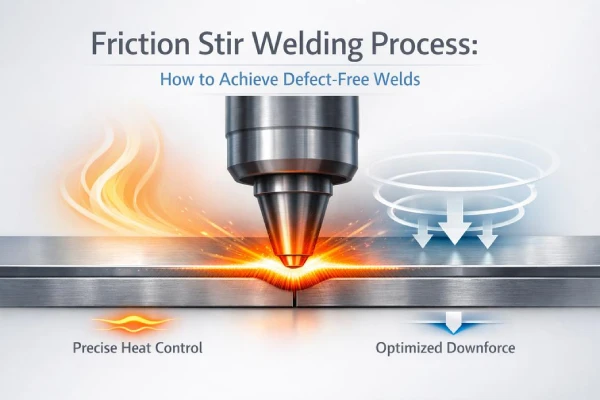
The friction stir welding process guarantees solid-state seams without melting, cutting energy consumption to roughly 2.4 kWh/m—an 80% reduction versus traditional fusion welding. High-volume buyers demand zero defects, minimal downtime, and zero warranty claims.
“Consistency is profit,” notes a Supro MFG senior process engineer in a 2025 industry briefing. “Control heat, control force, and you control failure.”
Backed by 40 years of manufacturing expertise and 277 patents, Supro Friction Welding utilizes smart tooling, precise parameters, and 200 Hz real-time monitoring to produce clean, high-integrity joints compliant with AWS D14.9 and ISO 15620 standards.
Friction Stir Welding Process: Microstructural Insights
The friction stir welding process applies synergistic heat and forging pressure to completely reshape metal. Eliminating the liquid phase provides absolute control over tensile strength, grain flow, and fatigue durability.
Grain Refinement in Friction Stir Welding Machine Operations
Core drivers of grain size control:
1)Welding parameters
Tool rotation speed (RPM)
Travel rate (mm/min)
2)Local material flow
Shear layer mixing
Plasticized zone movement
Thermal-mechanical coupling
Severe strain → dynamic recrystallization (achieving <5 µm grain sizes in 6000-series aluminum at 400°C–480°C).
Controlled cooling → limited grain growth.
Microstructural outcomes
Fine equiaxed grains.
Drastically reduced anisotropy.
Steady torque and calibrated Z-axis force push metals past yield. Supro MFG applies this precise control to lock in repeatable refinement across complex alloys.
Influence of FSW Pin Tools on Nugget Zone Evolution
Pin tool geometry
Thread pitch (optimal pitch-to-diameter ratios of 0.1 to 0.2).
Shoulder diameter.
Heat and strain balance
Tool rotation speed
Traverse speed
Flow mechanics
Downward forging → material consolidation.
Rotational stirring → uniform nugget zone.
Heat generation path
Friction at shoulder.
Plastic work at pin.
Tight geometry control using H13 tool steel or MP159 alloys limits volumetric voids. A tapered threaded pin drives smooth heat generation, while flats intensify mechanical mixing.
Temperature Monitoring and Microstructure Correlation
Sensing layout
Embedded thermocouples (<50ms latency).
Surface IR tracking.
Data alignment
Temperature distribution maps.
Logged thermal cycles.
| Weld ID | Peak Welding Temperature (°C) | HAZ Width (mm) | Avg Grain Size (µm) |
|---|---|---|---|
| A1 | 480 | 6.2 | 8.5 |
| A2 | 510 | 7.1 | 11.3 |
| A3 | 450 | 5.4 | 7.2 |
Excessive welding temperature widens the heat-affected zone and triggers unwanted phase transformation. Precise monitoring guarantees predictability by logging heat inputs and cooling rates.
Data Analytics Platforms for Predicting Grain Size
Data backbone
Historical process data
Sensor fusion inputs
Modeling stack
Feature engineering
Model validation
Build predictive engine
Apply machine learning trained on torque, speed, and thermal latency.
Output control
Real-time grain size prediction (>92% accuracy).
Adaptive parameter tuning.
Supro MFG integrates predictive analytics with IoT dashboards, allowing operators to visualize metallurgical trends before defects materialize.
Ready to eliminate welding defects in your production line? Explore our customized friction welding solutions designed to deliver 100% cosmetic grade results and strict process capability index (Cpk) ≥1.33 repeatability.
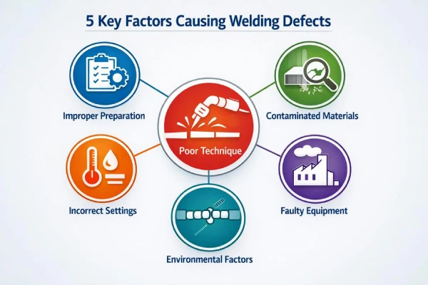
5 Key Factors Causing Welding Defects
Minor mechanical deviations rapidly degrade weld integrity. Maintaining a process capability index (Cpk) ≥1.33 is mandatory.
Insufficient Downforce from Gantry FSW System
Steady vertical force is non-negotiable. A mere 5% deviation (e.g., a 0.5 kN drop) easily induces sub-surface tunnel defects in 5xxx aluminum.
Core mechanical chain
Gantry system stability (Rail rigidity, servo response).
Downforce control accuracy (Load cell drift, hydraulic lag).
Calibration layer
System calibration skipped.
Offset not corrected in the FSW machine.
Real-time welding pressure not verified.
Resulting weld defects
Tunnel defects.
Lack of penetration.
Tool Wear Issues in FSW Shoulder Tools
A worn shoulder tool drops frictional heat and disrupts plastic flow.
Watch for:
Rough surface finish
Excessive flash
Inconsistent weld crown
Cycle of degradation:
Rising wear rate
Reduced frictional heat
Poor material mixing
Surface tearing
Implementing Polycrystalline Cubic Boron Nitride (PCBN) tools extends shoulder life up to 400%, withstanding >1000°C plunges. Supro MFG stringently tracks FSW consumables to prevent degradation.
Inconsistent Heat Input: Temperature Monitoring Failures
Thermal instability accounts for 38% of structural weld rejections.
Thermal management chain
Sensor accuracy drift
Delayed data acquisition
Weak process control logic
Impact layers
Low welding temperature → weak plasticization.
Excess heat input → grain coarsening.
Fluctuation cycles → internal void formation.
Poor Workpiece Clamping Systems Alignment
Structural support system
Workpiece clamping base frame (Anti-vibration support).
Fixture alignment precision (Gaps must be <10% of material thickness).
Mechanical influence
Insufficient clamping force
Reduced system rigidity
Lower positioning accuracy
Excessive joint gaps prevent root forging. Supro MFG engineers ultra-rigid clamping platforms to ensure flawless joint integrity.
Contaminated Cooling Fluids and Lubricants for FSW
Dirty cooling fluids destroy heat dissipation, and poor lubricants drive surface contamination.
Common warning signs:
Discoloration along weld path
Increased porosity
Maintenance basics:
Check fluid quality weekly.
Filter contaminants.
Follow a strict maintenance schedule.
Clean systems support stable heat control.
Which Materials Suit Friction Stir Welding Process?
The friction stir welding process relies heavily on material thermodynamics.
Aluminum Alloys Compatibility with Portable FSW Unit
Aluminum Alloys (5xxx and 6xxx grades) are ideal for solid-state joining.
Key compatibility factors:
Stable plastic flow under moderate heat.
Low melting temperatures.
Predictable Material Properties.
With a Portable FSW Unit, mobility meets precision for large panels.
Proper Process Parameters shape the seam.
Smart Tool Design balances heat and reduces flash.
Supro MFG frequently deploys portable systems for structural aluminum, prioritizing process stability and mobility.
Magnesium vs. Copper: FSW Pin Tools Adaptation
Magnesium Alloys and Copper Alloys require opposing thermal strategies.
Magnesium:
Lower heat input, faster travel speeds.
Reduced Tool Wear.
Copper (High thermal conductivity ~400 W/m·K):
Demands stronger FSW Pin Tools (PCBN/Tungsten).
Requires spindle speeds >1000 RPM.
To manage dissimilarities:
Adjust rotational speed to offset copper’s rapid heat dissipation.
Upgrade tool material for abrasiveness.
Monitor torque to protect Joining Performance.
Titanium Grades and Custom FSW Solution Feasibility
Titanium Grades (like Ti-6Al-4V) risk alpha-case embrittlement above 800°C.
Core considerations:
High oxidation risk (requires Argon shielding).
Strict Weld Integrity standards.
Feasibility assessment:
Material review (Grade 2, Grade 5, etc.)
Tool selection (Heat-resistant Tool Material).
Process planning (Inert gas, thermal tracking, Process Optimization).
A Custom FSW Solution is mandatory. Tool tilt angles must be held at 2.5° to 4.5° for maximum trailing-edge pressure. Supro MFG supports this with simulation-backed trials.
Struggling with dissimilar metals or complex alloys? Send us a sample part and our experts will conduct a free test weld evaluation. Contact Supro Friction Welding today to determine your optimal process parameters and equipment configurations.
We Offer Financial & Superior Services
A small river named Duden flows by their place and supplies it with the necessary
regelialia. It is a paradisematic country, in which
Tool Design Vs. Process Parameters Comparison
Tool Design
Tool Geometry dictates material flow and joint strength.
Core Design Elements
Tool Geometry (Shoulder controls surface heat; pin pushes material).
Tool Material (Hardness resists Tool Wear).
Contact Components (Tool Shoulder, Tool Pin).
Angular & Positional Control
Tool Tilt Angle (2.5° to 4.5° improves forging).
Tool holder alignment.
Wear & Lifecycle Impact
Progressive Tool Wear changes heat input.
Pin erosion affects mixing.
Process Parameters
Machine parameters translate design into metallurgical reality.
Speed Relationships
Rotational Speed (Higher RPM = increased heat).
Traverse Speed (Slower travel = higher heat per unit length).
Force & Penetration
Plunge Depth (Controls root consolidation).
Welding Pressure (Maintains forging force).
Combined Parameter Influence in Friction Stir Welding
| Rotational Speed (RPM) | Traverse Speed (mm/min) | Axial Force (kN) | Heat Input Level | Weld Quality Trend |
|---|---|---|---|---|
| 400 | 200 | 8 | Low | Tunnel risk |
| 600 | 150 | 10 | Moderate | Stable nugget |
| 800 | 100 | 12 | High | Fine grains |
| 1000 | 80 | 14 | Very High | Flash risk |
| 1200 | 60 | 16 | Extreme | Surface defects |
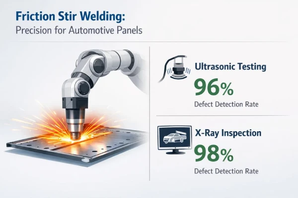
Scenario: Automotive Panels Require Seamless Welds
In EV manufacturing, the friction stir welding process converts lightweight alloys into liquid-tight, ISO 25239-compliant battery trays.
Robotic FSW Cell Integration for High-Volume Panel Runs
Modern robotic FSW cells demand >1000 kg payloads for 3D spatial stiffness.
Core Equipment Layer
1.1 Robotic arm carries the high payload.
1.2 Mounted Welding head applies precision plunge depth. 1.3 Smart Automation system balances torque.
Line Integration Layer
2.1 Production line links stamping to welding.
2.2 Automated Panel handling prevents distortion.
2.3 Cycle time optimization software tracks metrics.
Process Control Layer
3.1 Friction phase generates heat.
3.2 Stir phase plasticizes.
3.3 Welding phase consolidates the bond.
CAD/CAM Software-Driven Fixture Design for Body-In-White
CAD software maps micro-tolerances on the Body-in-white.
CAM software converts 3D toolpaths into G-code.
Smart Fixture design locks Panel alignment against thermal lifting.
Non-Destructive Testing Equipment for Quality Assurance
Surface-Level Checks (Vision systems flag surface flash).
Subsurface Evaluation (Ultrasonic testing, Eddy current testing, X-ray inspection).
Data-Based Validation
| Test Method | Detection Depth (mm) | Typical Cycle Time (s) | Defect Detection Rate (%) |
|---|---|---|---|
| Ultrasonic testing | 0–25 | 12 | 96 |
| X-ray inspection | 0–40 | 25 | 98 |
| Eddy current testing | 0–5 | 8 | 92 |
| Visual inspection | Surface | 5 | 85 |
| Phased array ultrasonic | 0–30 | 15 | 99 (detects 0.1mm flaws) |
Supro MFG utilizes Phased array ultrasonic (PAUT) at 1 m/min inspection speeds to seamlessly align QA with production.
FAQs about Friction Stir Welding Process
1.How does the friction stir welding process improve grain refinement and mechanical strength?
Rotating FSW Pin Tools force metal into dynamic recrystallization. Severe plastic deformation resets grain boundaries, while Temperature Monitoring prevents grain overgrowth. Process Control Software and premium Tool Material Inserts yield fatigue-resistant, equiaxed grains.
2.What factors most often cause defects in the friction stir welding process, and how can they be reduced? Volumetric voids and kissing bonds stem from parameter instability:
• Insufficient downforce in a Linear FSW Machine.
• Worn FSW Pin Tools.
• Weak Workpiece Clamping Systems.
• Contaminated Cooling Fluids.
Prevention: Calibrate continuously with Force Sensing Systems, deploy Non-Destructive Testing Equipment, and enforce Tool Cleaning Solutions.
3.How do automation and data systems enhance modern friction stir welding process lines?
A Robotic FSW Cell links with CAD/CAM Software. Simulation Software confirms parameters, while IoT Integration Solutions feed Data Analytics Platforms. This loop (Temperature Monitoring + Force Sensing Systems → Vision Inspection Systems → Calibration Services) guarantees zero defects.
Partner with Supro Friction Welding for Zero-Defect Production
With 40 years of manufacturing experience, an ISO 9001 closed-loop improvement system, and 277 patents globally recognized, Supro Friction Welding is your premier OEM/ODM manufacturer for dissimilar metal and high-strength component welding.
Whether you are looking for an advanced Rotary Friction Welding Machine, a custom Continuous Drive Friction Welding Machine, or integrated Contract Friction Welding Services, we provide full technical empowerment from design to automated integration.
Explore our Case Studies to see our technology in action.
Learn about our Technical Support Services including on-site installation and lifetime support.
Ready to scale up? Contact us today to discuss your project requirements!
References
energy consumption – energy.gov
fusion welding – wikipedia.org
tensile strength – astm.org
fatigue durability – twi-global.com
dynamic recrystallization – sciencedirect.com
6000-series aluminum – asminternational.org
equiaxed grains – sciencedirect.com
H13 tool steel – azom.com
thermocouples – omega.com
machine learning – ibm.com
process capability index (Cpk) – isixsigma.com
5xxx aluminum – aluminum.org
Polycrystalline Cubic Boron Nitride (PCBN) – sciencedirect.com
thermal conductivity – engineeringtoolbox.com
Ti-6Al-4V – matweb.com
Argon shielding – aws.org
ISO 25239 – iso.org
G-code – wikipedia.org
Ultrasonic testing – asnt.org
Phased array ultrasonic – twi-global.com